Introduction
Welcome to the user documentation for the qoqo/roqoqo quantum computing toolkit.
This user documentation gives a general overview of the design principles and intended usage scenarios for qoqo and roqoqo. For a detailed description of all the types and functions, see the API-documentation of roqoqo and qoqo.
What are qoqo and roqoqo
The qoqo and roqoqo packages are a pair of quantum computing toolkits by HQS Quantum Simulations.
Like many quantum toolkits, qoqo and roqoqo are circuit-based toolkits, at the core. A sequence of operations to be run on a quantum computer is grouped into a quantum circuit.
In the majority of quantum computing applications, the output of several quantum circuits needs to be collected and processed using additional classical measurement input, in order to construct a usable measurement result (e.g. when using a quantum computer to simulate physical quantum systems).
qoqo and roqoqo also provide tools to group quantum circuits and measurement input into a QuantumProgram. QuantumPrograms are designed as a high-level interface to quantum computations that can be used similar to standard function calls. QuantumPrograms accept floating point inputs, can be serialized, and only need qoqo/roqoqo and a simulator or a hardware backend to be executed.
What roqoqo/qoqo is
- A toolkit to represent quantum operations and circuits
- A tool to package quantum circuits and classical information into quantum programs
- A way to serialize quantum programs
- A set of optional interfaces to devices, simulators and toolkits (e.g. qoqo_quest, qoqo_mock, qoqo_qasm)
What roqoqo/qoqo is not
- A decomposer translating circuits to a specific set of gates
- A quantum circuit optimizer
- A collection of quantum algorithms
qoqo vs roqoqo
roqoqo is the core implementation of the toolkit. It is written in Rust. qoqo is the Python interface to roqoqo and provides operations, Circuit, measurements and QuantumProgram from roqoqo in the Python environment.
Architecture
roqoqo has several components:
- Operations and Circuit (see Quantum Circuits)
- Measurements and QuantumProgram (see High-Level Interface: Quantum Programs)
- Backends (see Backends)
- Devices (see Devices)
Operations and Circuit can be used to represent single quantum circuits that run on quantum hardware.
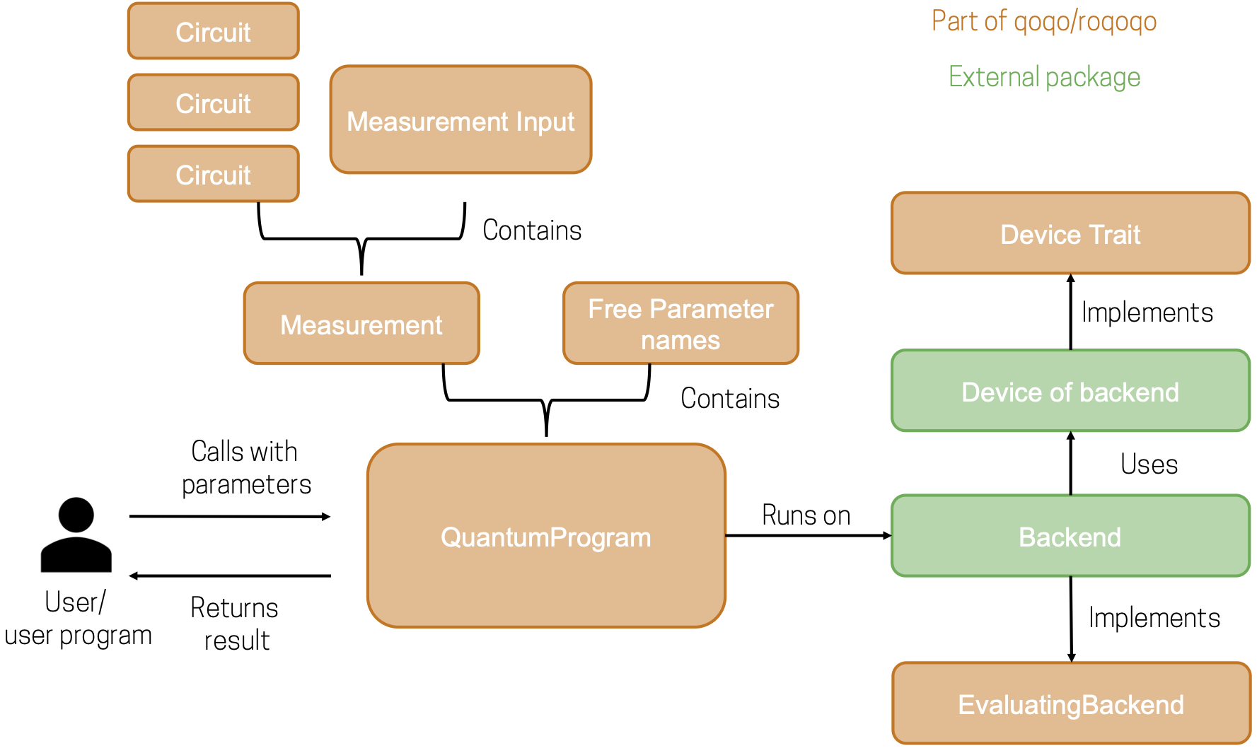
Measurements and QuantumProgram combine several circuits with classical information, to provide a high-level interface for running quantum programs that yield an immediately usable result.
To execute quantum circuits or quantum programs, a backend connecting to quantum hardware or a simulator is required.
qoqo/roqoqo does not directly implement these backends. To minimize dependencies, backends are implemented in separate packages (e.g. qoqo-quest).
In the backends module roqoqo provides an interface description for backends with the EvaluatingBackend Rust trait.
When compiling quantum circuits, it is often necessary to know the topology of a target quantum device. Device properties can also be used by backends, for example to accurately simulate a given quantum device.
qoqo/roqoqo defines an interface for obtaining the device topology and the noise properties. The interface is defined by roqoqo's Device trait. Additionally qoqo/roqoqo provides some simple devices that can be used to quickly define simple device topologies.
The following schematic shows how the different components are related when running a quantum program:
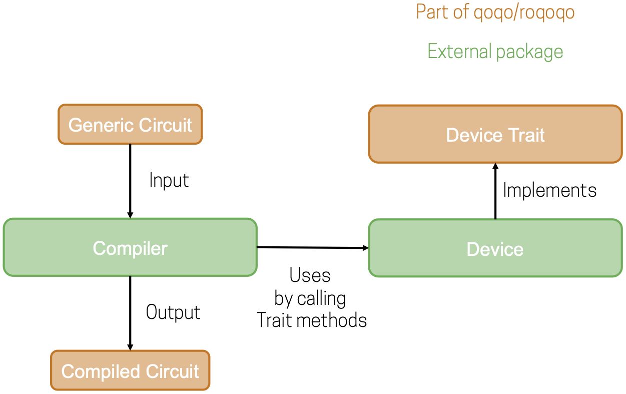
The circuit compilation use cases can be visualized in a similar way:
Installation
qoqo
qoqo is available on PyPi, both as a pre-built Python wheel for common architectures (windows/linux/macos on x86) and as a source distribution.
For pre-built wheels you can install qoqo with a simple pip command
pip install qoqo
If no pre-built python wheel is available for your architecture you can install qoqo from the source distribution using a rust toolchain (for example available via rustup) and maturin (also available via pip). After installing the rust toolchain and maturing run the same pip install command as above. In some cases on macOS it can be necessary to provide specific linker arguments as shown below:
# can be necessary on macOS
RUSTFLAGS="-C link-arg=-undefined -C link-arg=dynamic_lookup" pip install qoqo
When using qoqo in a rust project providing a python interface add
qoqo = {version="1.0", default-features=false}
to the [dependencies] section of the project Cargo.toml.
Alternatively one can check out the latest tagged version from github and use the maturin tool to build a python package for qoqo locally and install it via pip. Please note that the package should be built from the top level directory of the workspace selecting the qoqo package with the -m qoqo/Cargo.toml option.
maturin build -m qoqo/Cargo.toml  --release
pip install target/wheels/<NAME_OF_WHEEL>
Specifically for macOS on Apple Silicon the following build command should be used:
RUSTFLAGS="-C link-arg=-undefined -C link-arg=dynamic_lookup" maturin build -m qoqo/Cargo.toml  --release
pip install target/wheels/$NAME_OF_WHEEL
roqoqo
To use roqoqo in a Rust project simply add
roqoqo = "1.4"
to the [dependencies] section in your Cargo.toml.
Quantum circuit
A quantum circuit refers to a linear sequence of operations that can be executed on a quantum computer. Like most quantum computing toolkits, qoqo/roqoqo provides a Circuit object and a set of Operations that can be added to a Circuit.
qoqo/roqoqo distinguishes between:
- Definitions: Operations that declare (and initialize) classical register values (see also here)
- Gate Operations: Unitary operations that can be executed on every unitary quantum computer (but might need to be decomposed into a sequence of native operations) (see also here)
- Pragma operations that are not generally available on all universal quantum computers (see pragma operations and noise operations )
In order to create a useful result, a Circuit in qoqo/roqoqo must contain:
- A definition of a classical register for readout
- Operations to change the state of the quantum computer, for example
RotateZorCNOTgate operations. - A measurement to return classical information based on the state of the quantum computer.
With qoqo, a Circuit can be constructed like this:
from qoqo import Circuit
from qoqo import operations as ops
# create a new circuit
circuit = Circuit()
# Define the readout for two qubits
circuit += ops.DefinitionBit(name="ro", length=2, is_output=True)
# Rotation around Z axis by pi/2 on qubit 0
circuit += ops.RotateZ(qubit=0, theta=1.57)
# Entangling qubits 0 and 1 with CNOT gate
circuit += ops.CNOT(control=0, target=1)
# Measuring the qubits
circuit += ops.MeasureQubit(qubit=0, readout="ro", readout_index=0)
circuit += ops.MeasureQubit(qubit=1, readout="ro", readout_index=1)
And with roqoqo, like this:
use roqoqo::{Circuit, operations::*};

// Create a new _modifiable_ circuit
let mut circuit = Circuit::new();
// Define the readout for two qubits
circuit += DefinitionBit::new("ro".to_string(), 2, true);
// Apply rotation around Z axis by pi/2 on qubit 0
circuit += RotateZ::new(0, 1.57.into());
// Establish entanglement between qubits 0 and 1
circuit += CNOT::new(0, 1);
// Measuring the qubits
circuit += MeasureQubit::new(0, "ro".to_string(), 0);
circuit += MeasureQubit::new(1, "ro".to_string(), 1);
For details on the available methods of a Circuit please refer to the API documentation of roqoqo and qoqo.
Unitary Operations
Unitary operations or gate operations are operations that can be executed on all universal quantum computers. The operations correspond to unitary transformations of the state of a quantum computer.
Unitary Matrix
Gate operations in qoqo/roqoqo provide a unitary_matrix() method that returns the definition of the gate in matrix form. This definition ignores the qubits the gates acts on to fit in the smallest possible matrix dimension.
- For single-qubit gates, the created matrix always corresponds to
qubit=0and has dimension 2x2. - For two-qubit gates, the created matrix always corresponds to
control=1,target=0and has dimension a 4x4. See also the state ordering conventions. - For multi-qubit gates, the created matrix always corresponds to
qubits=[0..N]whereNis the number of qubits in the qubit vector of the multi-qubit gate.
For a list of unitary operations see gate operations.
Readout
To obtain results from running a quantum circuit, the quantum computer needs to return classical information. qoqo/roqoqo uses register-based readouts where all classical information is returned from the quantum circuit using classical registers declared at the start of the circuit. Classical registers can contain three types of classical data:
- Bit (or bool)
- Float (f64/double)
- Complex.
Each register is declared in a Circuit by a Pragma operation setting the register name and a length. The Pragma operation also declares whether the register is an output or not.
After being declared at the start of the circuit, information is written to the registers in the Circuit by Measurement or Pragma operations.
If the register is declared as an output register, it is returned after the execution of the circuit.
A python example:
from qoqo import Circuit
from qoqo import operations as ops

circuit = Circuit()
# A bit register that is not returned
circuit += ops.DefinitionBit("bit_register", length=2, is_output=False)
# A float register that is returned
circuit += ops.DefinitionFloat("float_register", length=2, is_output=True)
# A complex register that is not returned
circuit += ops.DefinitionComplex("complex_register", length=3, is_output=False)
A Rust example:
use roqoqo::Circuit;
use roqoqo::operations;

fn main(){
let mut circuit = Circuit::new();
// A bit register of length 2 that is not returned
circuit += operations::DefinitionBit::new("bit_register".to_string(), 2, false);
// A float register of length 2 that is returned as an output of the circuit
circuit += operations::DefinitionFloat::new("float_register".to_string(), 2, true);
// A complex register of length 3 that is not returned as an output
circuit += operations::DefinitionComplex::new("complex_register".to_string(), 3, false);
}
Writing to registers
Information is written to registers by the MeasureQubit operation or Pragma operations in a quantum circuit.
- On quantum computing hardware only projective measurements into a bit register are available, that is a measurement in the
Z-basis yielding0or1. - On simulators one can also read out the full state vector or density matrix into a complex register.
MeasureQubit corresponds directly to a projectivce measurement. By definition, projective measurements are available on universal quantum computers.
PragmaRepeatedMeasurement is shorthand for repeatedly running the circuit and applying a projective measurement each time. While it is not necessarily available on every backend it is compatible with hardware quantum computers.
As shown in the example below, the operation MeasureQubit can be used to provide measurement instructions for each individual qubit. The input parameter qubit specifies the qubit to be measured, whereas the parameter readout_index defines the position in the classical register readout where the measurement value of the qubit is stored. The explicit assignment of a qubit measurement to a readout register index can be used to handle qubit remapping in a quantum circuit.
When supported by the backend, PragmaRepeatedMeasurement can be used instead of MeasureQubit command to provide the measurement instruction for all qubits in qubit_mapping that needs to be repeated N times (number_measurements). For further available Pragma measurement instructions, please refer to the section Pragma operations.
Setting up readouts in Python:
from qoqo import Circuit
from qoqo import operations as ops

circuit = Circuit()
# Add a Bit register to the circuit for the qubit readout
circuit += ops.DefinitionBit("bit_register", 2, is_output = True)
# Add measurement instructions for each qubit, when using hardware
circuit += ops.MeasureQubit(qubit=0, readout="bit_register", readout_index=0)
circuit += ops.MeasureQubit(qubit=1, readout="bit_register", readout_index=1)

# Alternatively, define a Complex register to readout the state vector
circuit += ops.DefinitionComplex("complex_register", 3, is_output = False)
# Measure the state vector when running the circuit on a simulator
circuit += ops.PragmaGetStateVector("complex_register", None)
Setting up readouts in Rust:
use roqoqo::Circuit;
use roqoqo::operations;


let mut circuit = Circuit::new();
// Add a Bit register to the circuit for the qubit readout
circuit += operations::DefinitionBit::new("bit_register".to_string(), 2, true);
// Add measurement instructions for each qubit, when using hardware
circuit += operations::MeasureQubit::new(0, "bit_register".to_string(), 0);
circuit += operations::MeasureQubit::new(1, "bit_register".to_string(), 1);

// Alternatively, define a Complex register to readout the state vector
circuit += operations::DefinitionComplex::new(
    "complex_register".to_string(), 3, false,
);
// Measure the state vector when running the circuit on a simulator
circuit += operations::PragmaGetStateVector::new(
    "complex_register".to_string(), None,
);
Pragma Operations
Pragma operations in qoqo/roqoqo are operations that are not part of the set of operations that can run on all universal quantum computers.
Pragma operations can be used to:
- Annotate a quantum circuit with additional information that is not necessary for execution (e.g.
PragmaGlobalPhase,PragmaStartDecompositionBlock) - Apply operations that lead to a repeated execution of a circuit (
PragmaRepeatedMeasurement,PragmaSetNumberOfMeasurements) - Apply operations that are only available on specific hardware (e.g.
PragmaChangeDevice,PragmaSleep) - Apply operations that are only available on a simulator (e.g.
PragmaSetStateVector,PragmaGetStateVector) - Model noise (see also)
- Model error sources (
PragmaOverrotation)
For a full list of available Pragma operations see the API documentation of roqoqo and qoqo.
Noise Operations
qoqo/roqoqo enables the user to construct finely controlled noise models. Noise acting on the quantum computer is modeled as noise operations acting on individual qubits in between each unitary gate applied on the quantum computer.
The noise operations can be directly added to a quantum circuit and can be simulated by compatible backends. Since noise cannot be actively controlled on a quantum computer normally, the noise operations are defined as Pragma operations in qoqo/roqoqo. The strength of the noise is determined by defining a gate_time and a rate. The noise Pragma operation affects the system as a Lindblad type noise acting on the system with the rate rate for the time gate_time.
Note: as long as gate times and rates are scaled inversely any kind of units can be used.
Example
For example we can add dephasing noise to qubit 0, damping noise to qubit 1, and depolarising noise to qubit 2 after a CNOT gate has been applied.
In Python:
from qoqo import Circuit
from qoqo import operations

circuit = Circuit()
circuit += operations.CNOT(0,1)
# Adding dephasing noise acting on gate 0 with gate_time 1.0 and rate 1e-3
circuit += operations.PragmaDephasing(qubit=0, gate_time=1.0, rate=1e-3)
circuit += operations.PragmaDamping(1, 1.0, 2e-3)
circuit += operations.PragmaDepolarising(3, 1.0, 5e-3)
In Rust:
use roqoqo::Circuit;
use roqoqo::operations;

let mut circuit = Circuit::new();
circuit += operations::CNOT::new(0,1);
// Adding dephasing noise acting on gate 0 with gate_time 1.0 and rate 1e-3
circuit += operations::PragmaDephasing::new(0, 1.0, 1e-3.into());
circuit += operations::PragmaDamping::new(1, 1.0, 2e-3.into());
circuit += operations::PragmaDepolarising::new(3, 1.0, 5e-3.into());
Superoperator representation
All noise operations in qoqo/roqoqo provide a superoperator() method that returns the definition of the noise operation in superoperator matrix form.
In the superoperator formalism, the density matrix of the system is rewritten as a vector in row-major form. Applying the noise to the quantum computer then corresponds to multiplying the vector with the superoperator matrix.
The superoperator matrix ignores the qubits the noise operation acts on to fit in the smallest possible matrix dimension.
For other methods available for noise operations see the API documentation of roqoqo and qoqo.
Noise operations
The single noise operations shown in the example above are:
PragmaDamping, which applies a pure damping error corresponding to zero temperature environments.PragmaDepolarising, which applies a depolarising noise.PragmaDephasing, which applies a pure dephasing noise.
For a stochastically unravelled combination of dephasing and depolarising, the user can choose to use the PragmaRandomNoise. The error rate of the depolaristion (depolarising_rate) and the error rate of the dephasing (dephasing_rate) are provided as input parameters for this random noise operation.
PragmaGeneralNoise
The most general noise can be modeled in qoqo by the PragmaGeneralNoise operation. This Pragma operation applies a noise term according to the given rates. The rates are represented by a 3x3 matrix:
\[ M = \begin{pmatrix} a & b & c \\ d & e & f \\ g & h & j \\ \end{pmatrix} \],
where the coefficients correspond to the following summands expanded from the first term of the non-coherent part of the Lindblad equation: \[ \frac{d}{dt}\rho = \sum_{i,j=0}^{2} M_{i,j} L_{i} \rho L_{j}^{\dagger} - \frac{1}{2} { L_{j}^{\dagger} L_i, \rho } \],
with \( L_0 = \sigma^{+} \), \( L_1 = \sigma^{-} \) and \( L_3 = \sigma_{z} \).
Applying a Pragma noise operation with a given gate_time corresponds to applying the full time-evolution under the Lindblad equation.
Error Pragmas that are not noise operations
qoqo/roqoqo also supports Pragma operations that lead to errors in the execution of the quantum program that do not correspond to applying physical noise to the system
PragmaOverrotation
This operation applies a statistical overrotation to the next rotation gate in the circuit, which matches the name given in the gate parameter of PragmaOverrotation and the involved qubits provided in qubits. The applied overrotation corresponds to adding a random number to the rotation angle.
The random number is drawn from a normal distribution with mean 0 and standard deviation whose variance is given by the input parameter variance, which is then multiplied by the amplitude parameter.
PragmaBoostNoise
This operation boosts noise and overrotations in the circuit. The input parameter noise_coefficient defines the coefficient by which the noise is boosted, i.e. the number by which the gate_time is multiplied.
PragmaSleep
This operation makes the quantum computer hardware, that provides this functionality, wait a given amount of time (sleep_time). Waiting for a given time can increase the effect of continuous noise on the result of running a quantum circuit. This is sometimes used in noise-extrapolation error mitigation techniques.
High-level interface: quantum programs
In the definition of qoqo/roqoqo, a quantum program accepts input from a user/calling function and runs operations on a quantum computer. It then returns an output in the form of expectation values, instead of raw output from the quantum computer.
To represent quantum programs qoqo/roqoqo provides QuantumProgram.
It is intended as a high-level interface between a complex program and the quantum computer, which can be called (almost) as easily as a normal function and handles variable replacement and the post-processing of the raw output of the quantum computer/simulator.
Measurements
Post-processing the raw output is handled by measurements.
For many applications, the measurement results of several circuits need to be combined to extract the required information.
Measurement objects group several quantum circuits and a measurement input that determines how the raw output is post-processed.
A qoqo measurement combines one optional constant_circuit that is always executed first and a list of circuits that are each executed after the constant circuit.
The type of measurement and measurement input depends on the type of readout used in the circuits.
The following measurements are available in qoqo/roqoqo:
The PauliZProduct measurement is based on measuring the product of PauliZ operators for given qubits. Combined with a basis rotation of the measured qubits, it can be used to measure arbitrary expectation values. It uses projective qubit readouts like MeasureQubit or PragmaRepeatedMeasurement. It can be run on real quantum computer hardware and simulators. For further details please refer to section PauliZProduct.
The ClassicalRegister measurement returns the raw output of the classical registers written during circuit execution.
The CheatedPauliZProduct measurement directly calculates operator expectation values from the expectation values of products of Pauli matrices. The Pauli product expectation values are read out by the PragmaGetPauliProduct operation. It can only be used on simulator backends.
The Cheated measurement calculates expectation values by directly extracting the state vector PragmaGetStateVector or the density matrix PragmaGetDensityMatrix from a simulator and applying matrix multiplication.
For examples how to construct measurement input and measurements see the pages for the separate measurement types.
Variable replacement
qoqo/roqoqo supports symbolic parameters in Operations, for example the rotation angles \( \theta \) in a RotateX gate operation. A Circuit with symbolic parameters cannot be executed on real hardware or simulated. The symbolic parameters need to be replaced with real floating point numbers first. A QuantumProgram contains a list of the free parameters (input_parameter_names).
When calling its run method, it replaces the free parameters with the given input, executes the measurement on the given backend and returns the result.
For an example how to run a QuantumProgram see here.
PauliZProduct Measurement
The PauliZProduct measurement is based on measuring the product of PauliZ operators for given qubits. Combined with a basis rotation of the measured qubits, it can be used to measure arbitrary expectation values. It uses projective qubit readouts like MeasureQubit or PragmaRepeatedMeasurement. It can be run on real quantum computer hardware and simulators.
As an example, let us consider the measurement of the following Hamiltonian
\[
\hat{H} = 0.1\cdot X + 0.2\cdot Z
\] where X and Z are Pauli operators. The target is to measure \(\hat{H} \) with respect to a state
\[
|\psi> = (|0> + |1>)/\sqrt{2}.
\].
The constant_circuit will be used to prepare the state \( |\psi> \) by applying the Hadamard gate. The given Hamiltonian includes X and Z terms that cannot be measured at the same time, since they are measured using different bases. The circuits list includes one quantum circuit that does not apply any additional gate and one circuit that rotates the qubit basis into the X-basis so that the expectation value <X> is equivalent to the measurement of <Z> in the new basis. In this example, each measured Pauli product contains only one Pauli operator. For the post-processing of the measured results, the PauliZProduct measurement needs two more inputs provided by the object PauliZProductInput:
- The definition of the measured Pauli products after basis transformations (
add_pauliz_product()), - The weights of the Pauli product expectation values in the final expectation values (
add_linear_exp_val()).
In general, one can measure the expectation values of the products of local Z operators, e.g. <Z0>, <Z1>, <Z0*Z1>, <Z0*Z3>, etc. The PauliZProductInput needs to define all of the products that are measured. In the given example, we will measure two products <Z0> after a rotation in the X basis (corresponding to <X0>) and <Z0> without a rotation before the measurement.
The PauliZProductInput also defines the weights of the products in the final result. In the example below, 0.1 is the coefficient for the first product and 0.2 for the second.
from qoqo import Circuit
from qoqo import operations as ops
from qoqo.measurements import PauliZProduct, PauliZProductInput

# initialize |psi>
init_circuit = Circuit()
init_circuit += ops.Hadamard(0)

# Z-basis measurement circuit with 1000 shots
z_circuit = Circuit()
z_circuit += ops.DefinitionBit("ro_z", 1, is_output=True)
z_circuit += ops.PragmaRepeatedMeasurement("ro_z", 1000, None)

# X-basis measurement circuit with 1000 shots
x_circuit = Circuit()
x_circuit += ops.DefinitionBit("ro_x", 1, is_output=True)
# Changing to the X basis with a Hadamard gate
x_circuit += ops.Hadamard(0)
x_circuit += ops.PragmaRepeatedMeasurement("ro_x", 1000, None)

# Preparing the measurement input for one qubit
# The PauliZProductInput starts with just the number of qubits
# and if to use a flipped measurements set.
measurement_input = PauliZProductInput(1, False)
# Next, pauli products are added to the PauliZProductInput
# Read out product of Z on site 0 for register ro_z (no basis change)
z_basis_index = measurement_input.add_pauliz_product("ro_z", [0,])
# Read out product of Z on site 0 for register ro_x
# (after basis change effectively a <X> measurement)
x_basis_index = measurement_input.add_pauliz_product("ro_x", [0,])

# Last, instructions how to combine the single expectation values
# into the total result are provided.
# Add a result (the expectation value of H) that is a combination of
# the PauliProduct expectation values.
measurement_input.add_linear_exp_val(
    "<H>", {x_basis_index: 0.1, z_basis_index: 0.2},
)

measurement = PauliZProduct(
   constant_circuit=init_circuit,
   circuits=[z_circuit, x_circuit],
   input=measurement_input,
)
The same example in Rust:
use roqoqo::{Circuit, operations::*};
use roqoqo::measurements::{PauliZProduct, PauliZProductInput};
use std::collections::HashMap;

// initialize |psi>
let mut init_circuit = Circuit::new();
init_circuit.add_operation(Hadamard::new(0));

// Z-basis measurement circuit with 1000 shots
let mut z_circuit = Circuit::new();
z_circuit.add_operation(DefinitionBit::new("ro_z".to_string(), 1, true));
z_circuit.add_operation(
    PragmaRepeatedMeasurement::new("ro_z".to_string(), 1000, None),
);

// X-basis measurement circuit with 1000 shots
let mut x_circuit = Circuit::new();
x_circuit.add_operation(DefinitionBit::new("ro_x".to_string(), 1, true));
// Changing to the X-basis with a Hadamard gate
x_circuit.add_operation(Hadamard::new(0));
x_circuit.add_operation(
    PragmaRepeatedMeasurement::new("ro_x".to_string(), 1000, None),
);

// Preparing the measurement input for one qubit
// The PauliZProductInput starts with just the number of qubits
// and if to use a flipped measurements set.
let mut measurement_input = PauliZProductInput::new(1, false);
// Next, pauli products are added to the PauliZProductInput
// Read out product of Z on site 0 for register ro_z (no basis change)
measurement_input
    .add_pauliz_product("ro_z".to_string(), vec![0])
    .unwrap();
// Read out product of Z on site 0 for register ro_x
// (after basis change effectively a <X> measurement)
measurement_input
    .add_pauliz_product("ro_x".to_string(), vec![0])
    .unwrap();

// Last, instructions how to combine the single expectation values
// into the total result are provided.
// Add a result (the expectation value of H) that is a combination
// of the PauliProduct expectation values.
measurement_input
    .add_linear_exp_val(
        "<H>".to_string(), HashMap::from([(0, 0.1), (1, 0.2)]),
    )
    .unwrap();

let measurement = PauliZProduct {
    input: measurement_input,
    circuits: vec![z_circuit.clone(), x_circuit.clone()],
    constant_circuit: Some(init_circuit.clone()),

println!("{:?}", measurement);
};
QuantumProgram and Variable-Replacement
A QuantumProgram allows the user to call it with a list of free float parameters.
It contains a measurement with quantum circuits that contain symbolic parameters. Circuits with symbolic parameters cannot be simulated or executed on real hardware. The symbolic parameters need to be replaced with real floating point numbers first. A QuantumProgram contains a list of the free parameters (input_parameter_names) and can automatically replace the parameters when it is executed. It replaces the parameters by its run methods and returns the result.
As an example we will use the measurement from PauliZProduct with a state|psi> parameterized by an angle between |0> and |1>.
In python:
from qoqo import Circuit
from qoqo import operations as ops
from qoqo.measurements import PauliZProduct, PauliZProductInput
from qoqo import QuantumProgram
from qoqo_quest import Backend

# initialize |psi>
init_circuit = Circuit()
# Apply a RotateY gate with a symbolic angle
# To execute the circuit this symbolic parameter must be replaced
# by a real number with the help of a QuantumProgram
init_circuit += ops.RotateX(0, "angle")

# Z-basis measurement circuit with 1000 shots
z_circuit = Circuit()
z_circuit += ops.DefinitionBit("ro_z", 1, is_output=True)
z_circuit += ops.PragmaRepeatedMeasurement("ro_z", 1000, None)

# X-basis measurement circuit with 1000 shots
x_circuit = Circuit()
x_circuit += ops.DefinitionBit("ro_x", 1, is_output=True)
# Changing to the X basis with a Hadamard gate
x_circuit += ops.Hadamard(0)
x_circuit += ops.PragmaRepeatedMeasurement("ro_x", 1000, None)

# Preparing the measurement input for one qubit
measurement_input = PauliZProductInput(1, False)
# Read out product of Z on site 0 for register ro_z (no basis change)
z_basis_index = measurement_input.add_pauliz_product("ro_z", [0,])
# Read out product of Z on site 0 for register ro_x
# (after basis change effectively a <X> measurement)
x_basis_index = measurement_input.add_pauliz_product("ro_x", [0,])

# Add a result (the expectation value of H) that is a combination of
# the PauliProduct expectation values.
measurement_input.add_linear_exp_val(
    "<H>", {x_basis_index: 0.1, z_basis_index: 0.2},
)

measurement = PauliZProduct(
   constant_circuit=init_circuit,
   circuits=[z_circuit, x_circuit],
   input=measurement_input,
)

# A quantum program is created from the measurement
# and "angle" is registered as a free input parameter.
# The QuantumProgram now has one free parameter
# that needs to set when executing it.
# The symbolic value angle in the circuits will be replaced
# by that free parameter during execution.
program = QuantumProgram(
   measurement=measurement,
   input_parameter_names=["angle"],
)

# To execute a QuantumProgram a backend needs to be defined.
# Create a backend simulating one qubit.
backend = Backend(1)

# Run QuantumProgram on the backend by setting the parameter value.
expectation_values = program.run(backend, [0.785])
In Rust:
use roqoqo::{Circuit, operations::*, QuantumProgram};
use roqoqo::measurements::{PauliZProduct, PauliZProductInput};
use roqoqo::backends::{EvaluatingBackend, RegisterResult};
use roqoqo_quest::Backend;
use std::collections::HashMap;

// initialize |psi>
let mut init_circuit = Circuit::new();
init_circuit.add_operation(RotateX::new(0, "angle".into()));

// Z-basis measurement circuit with 1000 shots
let mut z_circuit = Circuit::new();
z_circuit.add_operation(DefinitionBit::new("ro_z".to_string(), 1, true));
z_circuit.add_operation(
    PragmaRepeatedMeasurement::new("ro_z".to_string(), 1000, None),
);

// X-basis measurement circuit with 1000 shots
let mut x_circuit = Circuit::new();
x_circuit.add_operation(DefinitionBit::new("ro_x".to_string(), 1, true));
// Changing to the X-basis with a Hadamard gate
x_circuit.add_operation(Hadamard::new(0));
x_circuit.add_operation(
    PragmaRepeatedMeasurement::new("ro_x".to_string(), 1000, None),
);

// Preparing the measurement input for one qubit
let mut measurement_input = PauliZProductInput::new(1, false);
// Read out product of Z on site 0 for register ro_z (no basis change)
measurement_input
    .add_pauliz_product("ro_z".to_string(), vec![0])
    .unwrap();
// Read out product of Z on site 0 for register ro_x
// (after basis change effectively a <X> measurement)
measurement_input
    .add_pauliz_product("ro_x".to_string(), vec![0])
    .unwrap();

// Add a result (the expectation value of H) that is a combination
// of the PauliProduct expectation values.
measurement_input
    .add_linear_exp_val(
        "<H>".to_string(), HashMap::from([(0, 0.1), (1, 0.2)]),
    )
    .unwrap();

let measurement = PauliZProduct {
    input: measurement_input,
    circuits: vec![z_circuit.clone(), x_circuit.clone()],
    constant_circuit: Some(init_circuit.clone()),
};

// A quantum program is created from the measurement
// and "angle" is registered as a free input parameter.
// The QuantumProgram now has one free parameter
// that needs to set when executing it.
// The symbolic value angle in the circuits will be replaced
// by that free parameter during execution.
let program = QuantumProgram::PauliZProduct {
    measurement,
    input_parameter_names: vec!["angle".to_string()],
};

// To execute a QuantumProgram a backend needs to be defined.
// Create a backend simulating one qubit.
let backend = Backend::new(1);

// Run QuantumProgram on the backend by setting the parameter value.
let expectation_values = program.run(backend, &[0.785]).unwrap();
ClassicalRegister Measurement
A ClassicalRegister measurement returns the unprocessed register readouts of Circuits.
A ClassicalRegister measurement can be used when end-users want to perform their own post-processing, for instance when working with external tools that expect full measurement records.
The registers are returned as a tuple of three dictionaries/HashMaps:
- The collection of bit registers
- The collection of float registers
- The collection of complex registers
A ClassicalRegister measurement does not need a separate measurement_input since no post-processing takes place.
To distinguish between a method returning expectation values and a method returning registers, the method run_registers() is used when executing a ClassicalRegister measurement.
An example for running a ClassicalRegister measurement:
from qoqo import Circuit
from qoqo import operations as ops
from qoqo.measurements import ClassicalRegister
from qoqo import QuantumProgram
from qoqo_quest import Backend

# initialize |psi>
init_circuit = Circuit()
init_circuit += ops.Hadamard(0)

# Z-basis measurement circuit with 1000 shots
z_circuit = Circuit()
z_circuit += ops.DefinitionBit("ro_z", 1, is_output=True)
z_circuit += ops.PragmaRepeatedMeasurement("ro_z", 1000, None)

# X-basis measurement circuit with 1000 shots
x_circuit = Circuit()
x_circuit += ops.DefinitionBit("ro_x", 1, is_output=True)
# Changing to the X basis with a Hadamard gate
x_circuit += ops.Hadamard(0)
x_circuit += ops.PragmaRepeatedMeasurement("ro_x", 1000, None)

measurement = ClassicalRegister(
    constant_circuit=init_circuit,
    circuits=[z_circuit, x_circuit],
)

# A quantum program is created from the measurement
program = QuantumProgram(measurement=measurement, input_parameter_names=[])

# Create a backend simulating one qubit.
backend = Backend(1)

(bit_registers, float_registers, complex_registers) = program.run_registers(backend, [])
The same example in Rust:
use roqoqo::{Circuit, operations::*, registers::*, QuantumProgram};
use roqoqo::measurements::ClassicalRegister;
use roqoqo::backends::{EvaluatingBackend, RegisterResult};
use roqoqo_quest::Backend;
use std::collections::{HashMap, HashSet};

// initialize |psi>
let mut init_circuit = Circuit::new();
init_circuit.add_operation(Hadamard::new(0));

// Z-basis measurement circuit with 1000 shots
let mut z_circuit = Circuit::new();
z_circuit.add_operation(DefinitionBit::new("ro_z".to_string(), 1, true));
z_circuit.add_operation(
    PragmaRepeatedMeasurement::new("ro_z".to_string(), 1000, None),
);

// X-basis measurement circuit with 1000 shots
let mut x_circuit = Circuit::new();
x_circuit.add_operation(DefinitionBit::new("ro_x".to_string(), 1, true));
// Changing to the X-basis with a Hadamard gate
x_circuit.add_operation(Hadamard::new(0));
x_circuit.add_operation(
    PragmaRepeatedMeasurement::new("ro_x".to_string(), 1000, None),
);

let measurement = ClassicalRegister {
    circuits: vec![z_circuit.clone(), x_circuit.clone()],
    constant_circuit: Some(init_circuit.clone()),
};

// A quantum program is created from the measurement
let program = QuantumProgram::ClassicalRegister {
    measurement,
    input_parameter_names: vec![],
};

// Create a backend simulating one qubit
let backend = Backend::new(1);

let result: RegisterResult = program.run_registers(backend.clone(), &[]);
let result_registers: (
    HashMap<String, BitOutputRegister>,
    HashMap<String, FloatOutputRegister>,
    HashMap<String, ComplexOutputRegister>,
) = result.unwrap();
CheatedPauliZProduct Measurement
The CheatedPauliZProduct measurement in qoqo/roqoqo calculates expectation values based on the expectation values of products of Pauli operators. It uses the PragmaGetPauliProduct readout and can only be used on a simulator backend.
The measurement input CheatedPauliZProductInput registers Pauli products and combines the expectation values of Pauli products into results just like the measurement input of a PauliZProduct measurement. In contrast to the PauliZProductInput, however, the involved qubits of the Pauli product are defined in the PragmaGetPauliProduct and no basis rotation is necessary.
The expectation values of Pauli products are directly derived from the state of a simulator in the backend and are exact on the level of the numerical accuracy of the simulator. The CheatedPauliZProduct operation can be used to benchmark an algorithm, assuming that the statistical error due to a finite amount of projective measurements vanishes.
The CheatedPauliZProduct only requires running one Circuit compared to several for more complex PauliZProduct measurements and can be faster.
Example
The following code measures the same observable as the PauliZProduct example with the CheatedPauliZProduct measurement.
Example in python:
from qoqo import Circuit
from qoqo import operations as ops
from qoqo.measurements import CheatedPauliZProduct, CheatedPauliZProductInput
from qoqo_quest import Backend

# initialize |psi> = (|0> + |1>)/ sqrt(2)
circuit = Circuit()
circuit += ops.Hadamard(0)

# Add definition for z-Basis readout
circuit += ops.DefinitionBit("ro_z", 1, is_output=True)

# Add definition for x-Basis readout
circuit += ops.DefinitionBit("ro_x", 1, is_output=True)

# The dictionary of the pauli matrix to measure for each qubit in the product in the form {qubit: pauli}.
# Allowed values to be provided for 'pauli' are: 1 = PauliX, 2 = PauliY, 3 = PauliZ.
pauliz_products = {0: 3}
paulix_products = {0: 1}
# PragmaGetPauliProduct works only on simulators and can be used several
# times since no projective measurements are applied
circuit += ops.PragmaGetPauliProduct(qubit_paulis=pauliz_products, readout="ro_z", circuit=Circuit())
circuit += ops.PragmaGetPauliProduct(qubit_paulis=paulix_products, readout="ro_x", circuit=Circuit())

# Preparing the measurement input for CheatedPauliZProductInput
measurement_input = CheatedPauliZProductInput()
# Next, pauli products are added to the CheatedPauliZProductInput
x_basis_index = measurement_input.add_pauliz_product("ro_x")
z_basis_index = measurement_input.add_pauliz_product("ro_z")

# Add a result (the expectation value of H) that is a combination of
# the PauliProduct expectation values.
measurement_input.add_linear_exp_val(
    "<H>", {x_basis_index: 0.1, z_basis_index: 0.2},
)

measurement = CheatedPauliZProduct(
   constant_circuit=None,
   circuits=[circuit,],
   input=measurement_input,
)
backend = Backend(1)

result = backend.run_measurement(measurement)
print(result)
The same example in Rust:
use roqoqo::backends::{EvaluatingBackend, RegisterResult};
use roqoqo::measurements::{CheatedPauliZProduct, CheatedPauliZProductInput};
use roqoqo::{operations::*, Circuit, QuantumProgram};
use std::collections::HashMap;
use roqoqo_quest::Backend;

// initialize |psi>
let mut circuit = Circuit::new();
circuit.add_operation(Hadamard::new(0));

// Add definition for z-Basis readout
circuit.add_operation(DefinitionFloat::new("ro_z".to_string(), 1, true));
// Add definition for z-Basis readout
circuit.add_operation(DefinitionFloat::new("ro_x".to_string(), 1, true));
// PragmaGetPauliProduct works only on simulators and can be used several
// times since no projective measurements are applied
circuit.add_operation(PragmaGetPauliProduct::new(
    HashMap::from([(0, 3)]),
    "ro_z".to_string(),
    Circuit::new()),
);
circuit.add_operation(PragmaGetPauliProduct::new(
    HashMap::from([(0, 1)]),
    "ro_x".to_string(),
    Circuit::new()));

// Preparing the measurement input for CheatedPauliZProductInput

let mut measurement_input = CheatedPauliZProductInput::new();
// Next, pauli products are added to the PauliZProductInput
// Read out product of Z on site 0 for register ro_z (no basis change)
let index_z = measurement_input.add_pauliz_product("ro_z".to_string());
// Read out product of X on site 0 for register ro_x
let index_x = measurement_input.add_pauliz_product("ro_x".to_string());

// Last, instructions how to combine the single expectation values
// into the total result are provided.
// Add a result (the expectation value of H) that is a combination
// of the PauliProduct expectation values.
measurement_input
    .add_linear_exp_val("<H>".to_string(), HashMap::from([(index_z, 0.1), (index_x, 0.2)]))
    .unwrap();

let measurement = CheatedPauliZProduct {
    input: measurement_input,
    circuits: vec![circuit.clone()],
    constant_circuit: None,
};

// Now, the PauliZProduct measurement is prepared to be used
// in a QuantumProgram just like:
let program = QuantumProgram::CheatedPauliZProduct {
    measurement,
    input_parameter_names: vec![],
};

let backend = Backend::new(3);

let res = program.run(backend, &[]);
println!("{:?}", res);
Cheated Measurement
A Cheated measurement in qoqo/roqoqo reads out the state vector or the density matrix of a quantum computer and obtains expectation values by multiplying the matrix representation of the observable with the state vector or multiplying the operator with the density matrix and taking the trace (respectively).
Cheated measurements are only possible with simulator backends that can return the state vector or the density matrix of the quantum state. The expectation values are defined by a sparse matrix representation of the measured observables. Using Cheated measurements, expectation values can be obtained directly without decomposing operators into Pauli products and post-processing the raw output of quantum computers.
from qoqo import Circuit
from qoqo import operations as ops
from qoqo.measurements import Cheated, CheatedInput
from qoqo import QuantumProgram
from qoqo_quest import Backend
import numpy as np

# initialize |psi> = (|0> + |1>)/ sqrt(2)
circuit = Circuit()
circuit += ops.Hadamard(0)

# Add definition for state-vector readout
circuit += ops.DefinitionComplex("state_vec", 2, is_output=True)

# The dictionary of the pauli matrix to measure for each qubit in the product in the form {qubit: pauli}.
# Allowed values to be provided for 'pauli' are: 1 = PauliX, 2 = PauliY, 3 = PauliZ.
x_matrix = np.array([[0, 1],[1, 0]])
z_matrix = np.array([[1, 0],[0, -1]])
h_matrix = 0.1 * x_matrix + 0.2 * z_matrix
operator = [(0,0, 0.2), (0,1, 0.1), (1,0, 0.1), (1,1, -0.2)]
# Directly get the state vector from the simulator backend
circuit += ops.PragmaGetStateVector(readout="state_vec", circuit=Circuit())

# Preparing the measurement input for CheatedPauliZProductInput
measurement_input = CheatedInput(number_qubits=1)
# Add the measured operator
measurement_input.add_operator_exp_val(name="<H>", operator=operator, readout="state_vec")

measurement = Cheated(
   constant_circuit=None,
   circuits=[circuit,],
   input=measurement_input,
)
backend = Backend(1)

result = backend.run_measurement(measurement)
print(result)
use num_complex::Complex64;
use roqoqo::measurements::{Cheated, CheatedInput};
use roqoqo::operations as ops;
use roqoqo::prelude::EvaluatingBackend;
use roqoqo::Circuit;
use roqoqo_quest::Backend;

// initialize |psi> = (|0> + |1>)/ sqrt(2)
let mut circuit = Circuit::new();
circuit += ops::Hadamard::new(0);

// Add definition for state-vector readout
circuit += ops::DefinitionComplex::new("state_vec".to_string(), 2, true);

// Defining the sparse operator
let operator: Vec<(usize, usize, Complex64)> = vec![
   (0, 0, 0.2.into()),
   (0, 1, 0.1.into()),
   (1, 0, 0.1.into()),
   (1, 1, (-0.2).into()),
];
// Directly get the state vector from the simulator backend
circuit += ops::PragmaGetStateVector::new("state_vec".to_string(), None);

// Preparing the measurement input for CheatedPauliZProductInput
let mut measurement_input = CheatedInput::new(1);
// Add the measured operator
measurement_input.add_operator_exp_val("<H>".to_string(), operator, "state_vec".to_string()).unwrap();

let measurement = Cheated {
   constant_circuit: None,
   circuits: vec![circuit],
   input: measurement_input,
};
let backend = Backend::new(1);

let result = backend.run_measurement(&measurement);
println!("{:?}", result);
Backends
Backends in qoqo/roqoqo are used for two things:
- Running quantum programs and obtaining results from them
- Translating qoqo/roqoqo objects to other frameworks
Running quantum programs
To obtain results based on a quantum program (or quantum circuit) defined in qoqo/roqoqo, the program must run on a simulator or real quantum computing hardware.
For an individual simulator or hardware, a backend can be created that implements roqoqo's EvaluatingBackend trait and executes quantum circuits.
The implementation of individual backends is provided not in qoqo itself, but in other packages.
At the moment the following EvaluatingBackends are implemented for qoqo/roqoqo:
An EvaluatingBackend provides the functionality to run:
- A single circuit. The backend will execute just the circuit and return the measurement results of all registers in a tuple (bit-registers, float-registers, complex-registers). More details on registers can be found in section readout. All the postprocessing of the bare results needs to be done manually.
- A measurement. All circuits collected in the measurement are executed and the post-processed expectation values are returned.
- A quantum program. A qoqo QuantumProgram also handles replacement of symbolic variables. It provides its own
run()method and calls the given backend internally.
All evaluating backends provide the same methods: run_circuit(), run_measurement() or run_measurement_registers(), and run().
Example
A QuantumProgram is created to be executed on the qoqo_quest simulator backend. Here, all three options supported by an EvaluatingBackend are presented:
- to run a single circuit,
- to run a measurement, and
- to run a quantum program.
In python:
from qoqo import Circuit
from qoqo import operations as ops
from qoqo.measurements import PauliZProduct, PauliZProductInput
from qoqo import QuantumProgram
from qoqo_quest import Backend
# initialize |psi>
init_circuit = Circuit()
# Apply a RotateY gate with a symbolic angle
# To execute the circuit this symbolic parameter must replaced
# with a real number with the help of a QuantumProgram
init_circuit += ops.RotateX(0, "angle")
# Z-basis measurement circuit with 1000 shots
z_circuit = Circuit()
z_circuit += ops.DefinitionBit("ro_z", 1, is_output=True)
z_circuit += ops.PragmaRepeatedMeasurement("ro_z", 1000, None)
# X-basis measurement circuit with 1000 shots
x_circuit = Circuit()
x_circuit += ops.DefinitionBit("ro_x", 1, is_output=True)
# Changing to the X basis with a Hadamard gate
x_circuit += ops.Hadamard(0)
x_circuit += ops.PragmaRepeatedMeasurement("ro_x", 1000, None)

# Preparing the measurement input for one qubit
measurement_input = PauliZProductInput(1, False)
# Read out product of Z on site 0 for register ro_z (no basis change)
z_basis_index = measurement_input.add_pauliz_product("ro_z", [0,])
# Read out product of Z on site 0 for register ro_x
# (after basis change effectively a <X> measurement)
x_basis_index = measurement_input.add_pauliz_product("ro_x", [0,])

# Add a result (the expectation value of H) that is a combination of the PauliProduct
# expectation values
measurement_input.add_linear_exp_val("<H>", {x_basis_index: 0.1, z_basis_index: 0.2})

measurement = PauliZProduct(
   constant_circuit=init_circuit,
   circuits=[z_circuit, x_circuit],
   input=measurement_input,
)

# Here we show three alternative options that can be ran:
# a single circuit, a measurement, and a quantum program.

# Create a backend simulating one qubit
backend = Backend(1)

# a) Run a single circuit
(bit_registers, float_registers, complex_registers) = backend.run_circuit(z_circuit)

# b) To run a measurement we need to replace the free parameter by hand
executable_measurement = measurement.substitute_parameters({"angle": 0.2})
expectation_values = backend.run_measurement(executable_measurement)
print(expectation_values)

# c) Run a quantum program
# The QuantumProgram now has one free parameter that must be set when executing it.
# The symbolic value "angle" in the circuits will be replaced by that free parameter
# during execution.
program = QuantumProgram(measurement=measurement, input_parameter_names=["angle"])
# Run the program with 0.1 substituting `angle`
expectation_values = program.run(backend, [0.1])
In Rust:
use std::collections::HashMap;

use roqoqo::Circuit;
use roqoqo::operations as ops;
use roqoqo::measurements::{PauliZProduct, PauliZProductInput};
use roqoqo::QuantumProgram;
use roqoqo::prelude::EvaluatingBackend;
use roqoqo::prelude::Measure;
use roqoqo_quest::Backend;

// initialize |psi>
let mut init_circuit = Circuit::new();
// Apply a RotateY gate with a symbolic angle
// To execute the circuit this symbolic parameter needs to be replaced
// with a real number with the help of a QuantumProgram
init_circuit += ops::RotateX::new(0, "angle".into());
// Z-basis measurement circuit with 1000 shots
let mut z_circuit = Circuit::new();
z_circuit += ops::DefinitionBit::new("ro_z".to_string(), 1, true);
z_circuit += ops::PragmaRepeatedMeasurement::new("ro_z".to_string(), 1000, None);
// X-basis measurement circuit with 1000 shots
let mut x_circuit = Circuit::new();
x_circuit += ops::DefinitionBit::new("ro_x".to_string(), 1, true);
// Changing to the X basis with a Hadamard gate
x_circuit += ops::Hadamard::new(0);
x_circuit += ops::PragmaRepeatedMeasurement::new("ro_x".to_string(), 1000, None);

// Preparing the measurement input for one qubit
let mut measurement_input = PauliZProductInput::new(1, false);
// Read out product of Z on site 0 for register ro_z (no basis change)
let z_basis_index = measurement_input.add_pauliz_product("ro_z".to_string(), vec![0,]).unwrap();
// Read out product of Z on site 0 for register ro_x
// (after basis change effectively a <X> measurement)
let x_basis_index = measurement_input.add_pauliz_product("ro_x".to_string(), vec![0,]).unwrap();

//Add a result (the expectation value of H) that is a combination of the PauliProduct
// expectation values
let mut linear: HashMap<usize, f64> = HashMap::new();
linear.insert(x_basis_index, 0.1);
linear.insert(z_basis_index, 0.2);
measurement_input.add_linear_exp_val("<H>".to_string(), linear).unwrap();

let measurement = PauliZProduct{
   constant_circuit: Some(init_circuit),
   circuits: vec![z_circuit.clone(), x_circuit],
   input: measurement_input,
};

// Here we show three alternative options that can be ran:
// a single circuit, a measurement, and a quantum program.

// Create a backend simulating one qubit
let backend = Backend::new(1);

// a) Run a single circuit
let (_bit_registers, _float_registers, _complex_registers) = backend.run_circuit(&z_circuit).unwrap();

// b) To run a measurement we need to replace the free parameter by hand
let executable_measurement = measurement.substitute_parameters(HashMap::from([("angle".to_string(), 0.2)])).unwrap();
let expectation_values = backend.run_measurement(&executable_measurement).unwrap();
println!("{:?}", expectation_values);

// c) Run a quantum program
// The QuantumProgram now has one free parameter that must be set when executing it.
// The symbolic value "angle" in the circuits will be replaced by that free parameter
// during execution.
let program = QuantumProgram::PauliZProduct{ measurement, input_parameter_names: vec!["angle".to_string()]};
// Run the program with 0.1 substituting `angle`
let expectation_values = program.run(backend, &[0.1]).unwrap();
println!("{:?}", expectation_values);
Translating to other quantum computing frameworks
There are many open- and closed-source quantum frameworks. For some use cases, it may be advantageous to interface between qoqo and another quantum computing framework. Depending on the target framework, circuits containing an available subset of qoqo operations can be translated to other frameworks by backends. Backends that translate qoqo/roqoqo objects (for example Circuits) to other frameworks or representations do not implement the EvaluatingBackend.
At the moment, we have implemented one translating backend, from qoqo/roqoqo Circuits to qasm: qoqo_qasm.
Devices
When working with quantum circuits it is often necessary to know the topology of a target quantum device. Device properties can also be used by backends, for example to accurately simulate a given quantum device.
qoqo/roqoqo defines an interface for obtaining the device topology. The interface is defined by roqoqo's Device trait. Additionally qoqo/roqoqo provides some simple devices that can be used to quickly define simple device topologies.
Devices based on the roqoqo Device trait can be abstract devices or backend devices.
Abstract devices contain abstract information about the device topology and the available gates.
Backend devices are devices that are implemented by a roqoqo backend. They can specify additional information for accessing the device on the backend and can contain additional information. The devices also contain all the information of the abstract devices.
A typical example for abstract devices are linear chains of square lattices in which two-qubit gate operations are only available between neighboring qubits.
It is defined by the decoherence rates M and the (pseudo-)time needed to execute a quantum operation.
The matrix representation of the decoherence rates of the Lindblad equation can be obtained by calling the method qubit_decoherence_rates() of a device.
The time required for a gate operation can be obtained from the methods single_qubit_gate_time(), two_qubit_gate_time(), and multi_qubit_gate_time() for a specific type of gate (defined by its name) and the qubits the gate should act on.
The gate time method can also be used to query the topology and available gate operations on a device. If a specific type of gate operation is not available on the given qubits, the gate time method will return None.
For further details of the Device trait please refer to the API documentation of roqoqo::devices (Rust core)
Simple Devices
qoqo/roqoqo provide three simple devices
GenericDeviceAllToAllDeviceSquareLatticeDevice
The GenericDevice is the most basic device. It simply contains all available gate operations, the corresponding gate times and the decoherence rate for each qubit in internal HashMaps. It can be used to create custom devices and as a device interchange format. As part of the Device interface, each device can be exported as a GenericDevice with the to_generic_device function. The GenericDevice is also used to exchange device data via JSON files or REST API calls.
use roqoqo::devices::Device;
use roqoqo::devices::{GenericDevice, AllToAllDevice};
use ndarray::array;
// Create a two-qubit device
let mut generic_device = GenericDevice::new(2);
// Create a comparison two-qubit device with `RotateZ` and `CNOT` as the only gates and 1.0 as the default gate time
let all_to_all = AllToAllDevice::new(2, &["RotateZ".to_string()], &["CNOT".to_string()], 1.0);

generic_device.set_single_qubit_gate_time("RotateZ", 0, 1.0).unwrap();
generic_device.set_single_qubit_gate_time("RotateZ", 1, 1.0).unwrap();
generic_device.set_two_qubit_gate_time("CNOT", 0, 1, 1.0).unwrap();
generic_device.set_two_qubit_gate_time("CNOT", 1, 0, 1.0).unwrap();
assert_eq!(generic_device, all_to_all.to_generic_device());
from qoqo import devices
import numpy as np
# Create a two-qubit device
generic_device = devices.GenericDevice(2)
# Create a comparison two-qubit device with `RotateZ` and `CNOT` as the only gates and 1.0 as the default gate time
all_to_all = devices.AllToAllDevice(2, ["RotateZ"], ["CNOT"], 1.0)
generic_device.set_single_qubit_gate_time("RotateZ", 0, 1.0)
generic_device.set_single_qubit_gate_time("RotateZ", 1, 1.0)
generic_device.set_two_qubit_gate_time("CNOT", 0, 1, 1.0)
generic_device.set_two_qubit_gate_time("CNOT", 1, 0, 1.0)
assert generic_device == all_to_all.generic_device()
The AllToAllDevice can be used to quickly create a device with all-to-all connectivity. Additionally to the set_single_qubit_time type functions which are identical to the GenericDevice, it provides functions to set the gate time on all gates of a certain type and set the decoherence rates of all qubits. When setting these attributes for all of the qubits on the device, the AllToAllDevice uses a builder pattern, in order for the user to be able to chain such calls. This is demonstrated below.
use roqoqo::devices::Device;
use roqoqo::devices::{GenericDevice, AllToAllDevice};
use ndarray::array;

// Create a two-qubit device with `RotateZ` and `CNOT` as the only gates and 1.0 as the default gate time
let mut all_to_all = AllToAllDevice::new(2, &["RotateZ".to_string()], &["CNOT".to_string()], 1.0);
// Set a new time for all RotateZ gates
let mut all_to_all = all_to_all.set_all_single_qubit_gate_times("RotateZ", 2.0);
// Set a new time for all CNOT gates
let mut all_to_all = all_to_all.set_all_two_qubit_gate_times("CNOT", 0.1);
from qoqo import devices
import numpy as np
# Create a two-qubit device with `RotateZ` and `CNOT` as the only gates and 1.0 as the default gate time
all_to_all = devices.AllToAllDevice(2, ["RotateZ"], ["CNOT"], 1.0)
# Set a new time for all RotateZ gates and CNOT gates
all_to_all = all_to_all.set_all_single_qubit_gate_times("RotateZ", 2.0).set_all_two_qubit_gate_times("CNOT", 0.1)
The SquareLatticeDevice can be used to quickly initialize a device with two-qubit operations available between next-neighbours on a square lattice. The same methods as AllToAllDevice are available.
use roqoqo::devices::Device;
use roqoqo::devices::{SquareLatticeDevice};
let rows = 1;
let columns = 2;
// Create a two-qubit device with `RotateZ` and `CNOT` as the only gates and 1.0 as the default gate time
let square_lattice = SquareLatticeDevice::new(rows, columns, &["RotateZ".to_string()], &["CNOT".to_string()], 1.0);
from qoqo import devices
rows = 1
columns = 2
# Create a two-qubit device with `RotateZ` and `CNOT` as the only gates and 1.0 as the default gate time
square_lattice = devices.SquareLatticeDevice(rows, columns, ["RotateZ"], ["CNOT"], 1.0)
Conventions
This section gives a quick overview of some of the conventions used in qoqo/roqoqo.
Definitions
operation: An atomic instruction applied to a quantum computer (or simulated quantum computer).gate: Anoperationthat corresponds to a unitary transformation of the state of the quantum computer and can be implemented on all universal quantum computers.qubit: A quantum bit. Can be in a superposition of two basis states.Circuit: A linear sequence ofoperations.
Qubit states
For the two basis states of a single qubit we define
\[ \left| 0 \right> = \left|\textrm{false} \right> = \left| \uparrow \right> = \begin{pmatrix} 1 \\ 0 \end{pmatrix} \\ \].
\[ \left |1 \right> = \left|\textrm{true} \right> = \left| \downarrow \right> = \begin{pmatrix} 0 \\ 1 \end{pmatrix} \\ \].
Before any operations are applied in a circuit a quantum computer is always assumed to be in the zero state (all qubits in state |0>).
Note
This convention implies that |0> is the excited state with respect to the Z Pauli operator and |1> is the ground state. This is in contract with the physical implementation of qubits, where |0> typically corresponds to the state with lower energy and damping will lead to the system relaxing from |1> to |0>.
This means that in this convention, when identifying the qubits with spins with respect to the Z operator, the system starts out in the highest energy case and damping leads to a heating effect where the system population shifts to higher energy spin states.
Endianness
qoqo and roqoqo use little-endian encoding, where the least significant qubit is at the smallest memory address (or at the lowest index in a vector and at the rightmost entry when writing the qubit state as a sequence of 0 and 1 like a binary number).
For a two-qubit state space we write the states of the qubits in the following order: \[ \left|00 \right> = \textrm{state} 0 \\ \left|01 \right> = \textrm{state} 1 \\ \left|10 \right> = \textrm{state} 2 \\ \left|11 \right> = \textrm{state} 3 \\ \].
Operation order
When adding qoqo/roqoqo operations to circuits, the first operation added will be executed first. When writing qoqo/roqoqo operations, they are read left to right. This leads to an inversion of the order when transcribing to matrix form, where the matrix to the right acts first.
\[ \textrm{PauliX}(0) \cdot \textrm{PauliZ}(0) \\ = \textrm{PauliZ(0).unitary_matrix()} \cdot \textrm{PauliX(0).unitary_matrix()} \\ = \begin{pmatrix} 1 & 0 \\ 0 & -1 \end{pmatrix} \begin{pmatrix} 0 & 1 \\ 1 & 0 \end{pmatrix} \].
Qubit naming
qoqo uses a unified naming scheme for qubits in operations
- In single-qubit operations, the qubit is always referred to as
qubit, - In two-qubit gates, the two qubits are referred to as
controlandtarget, - In multi-qubit gates, the ordered list/vector of qubits the gates acts on is referred to as
qubits.
When initializing two-qubit gates, the control is always the first argumemt and target the second argument.
Unitary Matrix
Unitary operations in qoqo/roqoqo provide a unitary_matrix() method that returns the definition of the gate in matrix form. This definition ignores the qubits of the gate to fit in the smallest possible matrix dimension.
- For single-qubit gates, the created matrix always corresponds to
qubit=0and has a 2x2-dimension. - For two-qubit gates, the created matrix always corresponds to
control=1,target=0and is a 4x4-dimensional matrix. This convention corresponds to the little-endian encoding described above. - For multi-qubit gates, the created matrix always corresponds to
qubits=[0..N]whereNis the number of qubits in the qubit vector of the multi-qubit gate.
List of Gate Operations
Operations are the atomic instructions in any quantum program that can be represented by qoqo/roqoqo. Gate operations are single-, two- or multi-qubit unitary operations that apply a unitary transformation and can be executed on any universal quantum computer. Mathematically, a gate can be represented by a unitary matrix.
A list of the gate operations available in qoqo and roqoqo with their mathematical description is provided in this section. We differentiate between single-qubit gates acting on a single qubit, two-qubit gates applied on a pair of qubits and multi-qubit gates affecting a series of qubits.
Notation
- A rotation angle is usually annotated with \( \theta \) and its corresponding argument is
theta. - For the phase angle, the symbol \( \varphi \) is used.
- The rotation angle \( \phi \) in the x-y plane is addressed by the argument name
phi. - \( \sigma_x \), \( \sigma_y \), \( \sigma_z \) are the Pauli matrices X, Y, Z \[ \sigma_x = \begin{pmatrix} 0 & 1 \\ 1 & 0 \end{pmatrix} := X, \quad \sigma_y = \begin{pmatrix} 0 & -i \\ i & 0 \end{pmatrix} := Y, \quad \sigma_z = \begin{pmatrix} 1 & 0 \\ 0 & -1 \end{pmatrix} := Z \].
Single-qubit gates
| Gate | Short Description |
|---|---|
| Hadamard | The Hadamard gate, to create a superposition of states, and so to change the basis. |
| InvSqrtPauliX | The inverse square root of the PauliX gate \( e^{i \frac{\theta}{4} \sigma_x} \). |
| PauliX | The Pauli X gate, a rotation with a fixed angle of \( \frac{\pi}{2} \), corresponds to a "flip" on x-axis. |
| PauliY | The Pauli Y gate, a rotation with a fixed angle of \( \frac{\pi}{2} \), corresponds to a "flip" on y-axis. |
| PauliZ | The Pauli Z gate, a rotation with a fixed angle of \( \frac{\pi}{2} \), corresponds to a "flip" on z-axis. |
| PhaseShiftState0 | Rotation around z-axis by angle \(\theta\) applied on state \( \left |0 \right> \) results in a phase shift compared to RotateZ gate. |
| PhaseShiftState1 | Rotation around z-axis by angle \(\theta\) applied on state \( \left|1 \right> \) results in phase shift compared to RotateZ gate. |
| RotateAroundSphericalAxis | Implements a rotation around an axis in spherical coordinates. |
| RotateX | The rotation gate around x-axis \( e^{-i \frac{\theta}{2} \sigma_x} \). |
| RotateXY | Implements a rotation around an axis in the x-y plane, where the axis is defined by an angle/spherical coordinates. |
| RotateY | The rotation gate around y-axis \( e^{-i \frac{\theta}{2} \sigma_y} \). |
| RotateZ | The rotation gate around z-axis \( e^{-i \frac{\theta}{2} \sigma_z} \). |
| SGate | The S gate. |
| SqrtPauliX | The square root of the PauliX gate \( e^{-i \frac{\theta}{4} \sigma_x} \). |
| TGate | The T gate. |
Two-qubit gates
| Gate | Short Description |
|---|---|
| Bogoliubov | The Bogoliubov DeGennes interaction gate. |
| CNOT | The controlled not gate, e.g. to entangle two qubits. |
| ComplexPMInteraction | The complex hopping gate. |
| ControlledPauliY | The controlled PauliY gate. |
| ControlledPauliZ | The controlled PauliZ gate. |
| ControlledPhaseShift | The controlled phase shift gate. |
| Fsim | The fermionic qubit simulation gate. |
| FSwap | The fermionic SWAP gate. |
| GivensRotation | The Givens rotation interaction gate in big endian notation: \(e^{-\mathrm{i} \theta (X_c Y_t - Y_c X_t)}\cdot e^{-i \phi Z_t/2} \). |
| GivensRotationLittleEndian | The Givens rotation interaction gate in little-endian notation: \(e^{-\mathrm{i} \theta (X_c Y_t - Y_c X_t)}\cdot e^{-i \phi Z_c/2} \). |
| InvSqrtISwap | The inverse square root of the ISwap gate. |
| ISwap | The complex swap gate. |
| MolmerSorensenXX | The fixed-phase Mølmer–Sørensen XX gate. |
| PhaseShiftedControlledZ | The phased-shifted controlled-Z gate. |
| PMInteraction | The transversal interaction gate. |
| Qsim | The qubit simulation gate. |
| SpinInteraction | The generalized, anisotropic XYZ Heisenberg interaction between spins. |
| SqrtISwap | The square root of the ISwap gate. |
| SWAP | The swap gate, to switch the positions of two qubits. |
| VariablesMSXX | The variable-angle Mølmer–Sørensen XX gate. |
| XY | The XY gate. |
Multi-qubit gates
| Gate | Short Description |
|---|---|
| MultiQubitMS | The Mølmer–Sørensen gate between multiple qubits. |
| MultiQubitZZ | The multi-qubit PauliZ-product gate. |
Single-qubit gates
Single-qubit gates in qoqo/roqoqo represent atomic instructions of any quantum computer that act on a single qubit. In single-qubit gates the qubit is always referred to as qubit. The unitary matrices of single-qubit gates are 2x2-dimensional matrices applied on single-qubit states \( \left |0 \right> \) and \( \left |1 \right> \), as defined in chapter conventions.
The most general unitary operation acting on one qubit is of the form \[ U =e^{\mathrm{i} \phi}\begin{pmatrix} \alpha_r+\mathrm{i} \alpha_i & -\beta_r+\mathrm{i} \beta_i \\ \beta_r+\mathrm{i} \beta_i & \alpha_r-\mathrm{i}\alpha_i \end{pmatrix} \].
The parameters \( \alpha_r \), \( \alpha_i \) and \( \beta_r \), \( \beta_i \) can be accessed by the functions alpha_r(), alpha_i(), beta_r() and beta_i(), applied on the particular single-qubit gate. The full matrix form of the single-qubit gates available in qoqo/roqoqo is documented in this chapter.
GPi
The unitary matrix of the GPi gate, which is often used in the context of ion traps, is defined as follows:
\[ U = \begin{pmatrix} 0 & e^{-i \theta}\\ e^{i \theta} & 0 \end{pmatrix} \].
GPi2
The unitary matrix of the GPi2 gate, which is often used in the context of ion traps, is defined as follows:
\[ U = \frac{1}{\sqrt{2}} \begin{pmatrix} 1 & -i e^{-i \theta}\\ -i e^{i \theta} & 1 \end{pmatrix} \].
Hadamard
The Hadamard gate when applied creates a superposition of states, and can therefore be used to change the basis if required. The definition of the gate in matrix form is given by:
\[ U = \frac{1}{\sqrt{2}} \begin{pmatrix} 1 & 1 \\ 1 & -1 \end{pmatrix} \].
InvSqrtPauliX
The inverse square root of the PauliX gate \( e^{\mathrm{i} \frac{\theta}{4} \sigma_x} \) corresponds to a unitary matrix defined as:
\[ U = \frac{1}{\sqrt{2}} \begin{pmatrix} 1 & \mathrm{i} \\ \mathrm{i} & 1 \end{pmatrix} \].
On some hardware platforms, the gate operation InvSqrtPauliX together with the operation SqrtPauliX are the only available rotation gates. This becomes relevant when it comes to the compilation of a quantum algorithm containing any arbitrary gates to the set of basic gates supported by the hardware device.
PauliX
The Pauli X gate implements a rotation of \( \frac{\pi}{2} \) about the x-axis that can be used, for example, to flip the qubit state. The full matrix form is given by:
\[ U = \begin{pmatrix} 0 & 1 \\ 1 & 0 \end{pmatrix} \].
PauliY
The Pauli Y gate implements a rotation of \( \frac{\pi}{2} \) about the y-axis that can be used, for example, to flip the qubit state. The unitary matrix is defined as:
\[ U = \begin{pmatrix} 0 & -\mathrm{i} \\ \mathrm{i} & 0 \end{pmatrix} \].
PauliZ
The Pauli Z gate implements a rotation of \( \frac{\pi}{2} \) about the z-axis that can be used, for example, to flip the qubit state. The full matrix form is given by:
\[ U = \begin{pmatrix} 1 & 0 \\ 0 & -1 \end{pmatrix} \].
PhaseShiftState0
This gate operation corresponds to the phase shift gate applied on state \( \left |0 \right> \) compared to RotateZ gate. It implements a rotation around Z-axis by an arbitrary angle \(\theta\), also known as AC Stark shift of the state \( \left |0 \right> \). The unitary matrix is given by:
\[ U = \begin{pmatrix} e^{\mathrm{i} \theta} & 0\\ 0 & 1 \end{pmatrix} \].
PhaseShiftState1
This gate operation corresponds to the phase shift gate applied on state \( \left |1 \right> \) compared to RotateZ gate. It implements a rotation around Z-axis by an arbitrary angle \(\theta\), also known as AC Stark shift of the state \( \left |1 \right> \). The unitary matrix is given by:
\[ U = \begin{pmatrix} 1 & 0\\ 0 & e^{\mathrm{i} \theta} \end{pmatrix} \].
RotateAroundSphericalAxis
Implements a rotation around an axis in the x-y plane in spherical coordinates. The definition of the gate in matrix form is given by:
\[ U = \begin{pmatrix} \cos\left(\frac{\theta}{2}\right) & 0\\ 0 & \cos\left(\frac{\theta}{2}\right) \end{pmatrix} + \begin{pmatrix} -\mathrm{i} \sin\left(\frac{\theta}{2}\right) v_z & \sin\left(\frac{\theta}{2}\right) \left(-i v_x - v_y \right)\\ \sin\left(\frac{\theta}{2}\right) \left(-\mathrm{i} v_x + v_y \right) & \mathrm{i} \sin\left(\frac{\theta}{2}\right) v_z \end{pmatrix} \],
with \[ v_x = \sin\left(\theta_{sph}\right) \cdot \cos\left(\phi_{sph}\right), \quad v_y = \sin\left(\theta_{sph}\right)\cdot\sin\left(\phi_{sph}\right), \quad v_z = \cos\left(\theta_{sph}\right). \].
RotateX
The rotation gate around x-axis \( e^{-\mathrm{i} \frac{\theta}{2} \sigma_x} \). The definition of the unitary matrix is as follows:
\[ U = \begin{pmatrix} \cos(\frac{\theta}{2}) & -\mathrm{i} \sin(\frac{\theta}{2})\\ -\mathrm{i}\sin(\frac{\theta}{2}) & \cos(\frac{\theta}{2}) \end{pmatrix} \].
RotateXY
Implements a rotation around an axis in the x-y plane, where the axis is defined by an angle/spherical coordinates. The unitary matrix representing the gate is given by:
\[ U = \begin{pmatrix} \cos \left(\frac{\theta}{2} \right) & -\mathrm{i} e^{-\mathrm{i} \phi} \sin \left(\frac{\theta}{2} \right) \\ -\mathrm{i} e^{\mathrm{i} \phi} \sin \left( \frac{\theta}{2} \right) & \cos\left( \frac{\theta}{2} \right) \end{pmatrix} \].
RotateY
The rotation gate around the y-axis \( e^{-\mathrm{i} \frac{\theta}{2} \sigma_y} \). The full matrix form is given by:
\[ U = \begin{pmatrix} \cos(\frac{\theta}{2}) & - \sin(\frac{\theta}{2})\\ \sin(\frac{\theta}{2}) & \cos(\frac{\theta}{2}) \end{pmatrix} \].
RotateZ
The rotation gate around the z-axis \( e^{-\mathrm{i} \frac{\theta}{2} \sigma_z} \). The unitary matrix reads:
\[ U = \begin{pmatrix} \cos(\frac{\theta}{2}) -\mathrm{i} \sin(\frac{\theta}{2}) & 0\\ 0 & \cos(\frac{\theta}{2}) + \mathrm{i} \sin(\frac{\theta}{2}) \end{pmatrix} \].
SGate
The unitary matrix of the S gate, which is often used in the theory of error correction, reads:
\[ U = \frac{1}{\sqrt{2}} \begin{pmatrix} 1 & 0 \\ 0 & \mathrm{i} \end{pmatrix} \].
SqrtPauliX
The square root of the PauliX gate \( e^{-\mathrm{i} \frac{\theta}{4} \sigma_x} \). The full matrix form is given by:
\[ U = \frac{1}{\sqrt(2)}\begin{pmatrix} 1 & -\mathrm{i} \\ -\mathrm{i} & 1 \end{pmatrix} \].
On some hardware platforms, the gate operation SqrtPauliX together with the operation InvSqrtPauliX are the only available rotation gates. This becomes relevant when it comes to the compilation of a quantum algorithm containing any arbitrary gates to the set of basic gates supported by the hardware device.
TGate
The unitary matrix of the T gate, which is often used in the theory of error correction, is defined as follows:
\[ U = \frac{1}{\sqrt{2}} \begin{pmatrix} 1 & 0 \\ 0 & e^{\mathrm{i} \frac{\pi}{4}} \end{pmatrix} \].
Two-qubit gates
Two-qubit gates in qoqo/roqoqo represent atomic instructions of any quantum computer that act on a pair of qubits. In two-qubit gates the two qubits are referred to as control and target. When initializing two-qubit gates, the control is always the first argument and target the second argument. For two-qubit gates, the created matrix always corresponds to control=1, target=0, and is a 4x4-dimensional matrix. This convention corresponds to the little-endian encoding as described in chapter conventions. The full matrix form of the two-qubit gates implemented in qoqo/roqoqo is documented in this chapter.
The given form of the unitary matrix is consistent with the following ordering of qubit states in a two-qubit state space:
\[ \left|00 \right> = \textrm{state} 0 \\ \left|01 \right> = \textrm{state} 1 \\ \left|10 \right> = \textrm{state} 2 \\ \left|11 \right> = \textrm{state} 3 \\ \].
Bogoliubov
The Bogoliubov DeGennes gate representing interactions of the form: \[ e^{-\mathrm{i} \mathrm{Re}(\Delta)\cdot(X_c X_t - Y_c Y_t)/2 + \mathrm{Im}(\Delta)\cdot(X_c Y_t+Y_c X_t)/2}, \],
where \(X_c\) is the Pauli matrix \(\sigma_x\) acting on the control qubit, and \(Y_t\) is the Pauli matrix \(\sigma_y\) acting on the target qubit, and \( \Delta \) is the complex Bogoliubov interaction strength.
The full matrix form is given by:
\[ U = \begin{pmatrix} \cos(|\Delta|) & 0 & 0 & \mathrm{i} \sin(|\Delta|) e^{\mathrm{i} \cdot \varphi(\Delta)} \\ 0 & 1 & 0 & 0 \\ 0 & 0 & 1 & 0 \\ \mathrm{i} \sin(|\Delta|) e^{-\mathrm{i} \cdot \varphi(\Delta)} & 0 & 0 & \cos(|\Delta|) \end{pmatrix} \],
with the value \(|\Delta|\) of the complex Bogoliubov interaction strength \( \Delta \), and its phase angle \(\varphi(\Delta)\).
CNOT
The controlled not gate can be used to entangle two qubits. The unitary matrix for the CNOT gate is defined as:
\[ U = \begin{pmatrix} 1 & 0 & 0 & 0 \\ 0 & 1 & 0 & 0 \\ 0 & 0 & 0 & 1 \\ 0 & 0 & 1 & 0 \end{pmatrix} \].
ComplexPMInteraction
This gate implements the complex hopping operation of the form:
\[ e^{-\mathrm{i} \left[ \mathrm{Re}(\theta) \cdot (X_c X_t + Y_c Y_t) - \mathrm{Im}(\theta) \cdot (X_c Y_t - Y_c X_t) \right] } , \],
where \(X_c\) is the Pauli matrix \(\sigma_x\) acting on the control qubit, and \(Y_t\) is the Pauli matrix \(\sigma_y\) acting on the target qubit. The complex parameter \( \theta \) gives the strength of the rotation.
ControlledPauliY
The controlled PauliY gate applies the PauliY gate on the target qubit based on the value of the control qubit. The corresponding unitary matrix reads:
\[ U = \begin{pmatrix} 1 & 0 & 0 & 0 \\ 0 & 1 & 0 & 0 \\ 0 & 0 & 0 & -\mathrm{i} \\ 0 & 0 & \mathrm{i} & 0 \end{pmatrix} \].
ControlledPauliZ
The controlled PauliZ gate applies the PauliZ gate on the target qubit controlled by the control qubit. The definition for the unitary matrix is as follows:
\[ U = \begin{pmatrix} 1 & 0 & 0 & 0 \\ 0 & 1 & 0 & 0 \\ 0 & 0 & 1 & 0 \\ 0 & 0 & 0 & -1 \end{pmatrix} \].
ControlledPhaseShift
The controlled phase shift gate implements a phase shift applied on target qubit based on the value of the control qubit. The unitary matrix is given by:
\[ U = \begin{pmatrix} 1 & 0 & 0 & 0 \\ 0 & 1 & 0 & 0 \\ 0 & 0 & 1 & 0 \\ 0 & 0 & 0 & e^{\mathrm{i} \theta} \end{pmatrix} \].
ControlledRotateX
The controlled RotateX implements a RotateX gate applied on target qubit based on the value of the control qubit. The unitary matrix is given by:
\[ U = \begin{pmatrix} 1 & 0 & 0 & 0 \\ 0 & 1 & 0 & 0 \\ 0 & 0 & \cos(\frac{\theta}{2}) & -i \sin(\frac{\theta}{2}) \\ 0 & 0 & -i \sin(\frac{\theta}{2}) & \cos(\frac{\theta}{2}) \end{pmatrix} \].
ControlledRotateXY
The controlled RotateXY implements a RotateXY gate applied on target qubit based on the value of the control qubit. The unitary matrix is given by:
\[ U = \begin{pmatrix} 1 & 0 & 0 & 0 \\ 0 & 1 & 0 & 0 \\ 0 & 0 & \cos(\frac{\theta}{2}) & -i e^{-i \phi} \sin(\frac{\theta}{2}) \\ 0 & 0 & -i e^{-i \phi} \sin(\frac{\theta}{2}) & \cos(\frac{\theta}{2}) \end{pmatrix} \].
Fsim
The fermionic qubit simulation gate that can be represented as the following unitary matrix:
\[ U = \begin{pmatrix} \cos(\Delta) & 0 & 0 & \mathrm{i} \sin(\Delta) \\ 0 & -\mathrm{i} \sin(t) & \cos(t) & 0 \\ 0 & \cos(t) & -\mathrm{i} \sin(t) & 0 \\ -\sin(\Delta) \cdot e^{-\mathrm{i} U} & 0 & 0 & -\cos(\Delta) \cdot e^{-\mathrm{i} U} \end{pmatrix} \],
where t is the hopping strength, U is the interaction strength and \( \Delta \) is the Bogoliubov interaction strength.
Note: The qubits have to be adjacent, i.e., \( |i-j|=1 \) has to hold. This is the only case in which the gate is valid as a two-qubit gate (due to the Jordan-Wigner transformation).
FSwap
The fermionic SWAP gate can be represented as the following unitary matrix:
\[ U = \begin{pmatrix} 1 & 0 & 0 & 0 \\ 0 & 0 & 1 & 0 \\ 0 & 1 & 0 & 0 \\ 0 & 0 & 0 & -1 \end{pmatrix} \].
GivensRotation
The Givens rotation interaction gate in big endian notation: \[ e^{-\mathrm{i} \theta (X_c Y_t - Y_c X_t)}\cdot e^{-\mathrm{i} \phi Z_t/2}, \],
where \(X_c\) is the Pauli matrix \(\sigma_x\) acting on the control qubit, \(Y_t\) is the Pauli matrix \(\sigma_y\) acting on the target qubit, and \(Z_t\) is the Pauli matrix \(\sigma_z\) acting on the target qubit.
The unitary matrix representation is:
\[ U = \begin{pmatrix} 1 & 0 & 0 & 0 \\ 0 & \cos(\theta) \cdot e^{\mathrm{i} \phi} & \sin(\theta) & 0 \\ 0 & -\sin(\theta) \cdot e^{\mathrm{i} \phi} & \cos(\theta) & 0 \\ 0 & 0 & 0 & e^{\mathrm{i} \phi} \end{pmatrix} \].
Further information on the endianness in context of qoqo can be found in the section conventions.
GivensRotationLittleEndian
The Givens rotation interaction gate in little-endian notation:
\[
e^{-\mathrm{i} \theta (X_c Y_t - Y_c X_t)}\cdot e^{-\mathrm{i} \phi Z_c/2},
\],
with Pauli matrices \( X := \sigma_x\), \( Y := \sigma_y\), \( Z := \sigma_z\) and indices c for control qubit and t for target qubit.
The unitary matrix form is given by:
\[ U = \begin{pmatrix} 1 & 0 & 0 & 0 \\ 0 & \cos(\theta) & \sin(\theta) & 0 \\ 0 & -\sin(\theta) \cdot e^{\mathrm{i} \phi} & \cos(\theta) \cdot e^{\mathrm{i} \phi} & 0 \\ 0 & 0 & 0 & e^{\mathrm{i} \phi} \end{pmatrix} \].
InvSqrtISwap
The inverse square root of the ISwap gate has the full matrix form:
\[ U = \begin{pmatrix} 1 & 0 & 0 & 0 \\ 0 & \frac{1}{\sqrt{2}} & \frac{-\mathrm{i}}{\sqrt{2}} & 0 \\ 0 & \frac{-\mathrm{i}}{\sqrt{2}} & \frac{1}{\sqrt{2}} & 0 \\ 0 & 0 & 0 & 1 \end{pmatrix} \].
ISwap
The unitary matrix of the complex ISwap gate reads:
\[ U = \begin{pmatrix} 1 & 0 & 0 & 0 \\ 0 & 0 & \mathrm{i} & 0 \\ 0 & \mathrm{i} & 0 & 0 \\ 0 & 0 & 0 & 1 \end{pmatrix} \].
MolmerSorensenXX
This gate implements the fixed-phase MolmerSorensen XX operation as introduced in this reference. The MolmerSorensenXX gate can be used to represent global laser-driver entangling operations, for example in the context of quantum computing hardware based on trapped ions. The unitary matrix is given by:
\[ U = \frac{1}{\sqrt{2}} \begin{pmatrix} 1 & 0 & 0 & -\mathrm{i} \\ 0 &1 & -\mathrm{i} & 0 \\ 0 & -\mathrm{i} & 1 & 0 \\ -\mathrm{i} & 0 & 0 & 1 \end{pmatrix} \].
PhaseShiftedControlledPhase
The phase-shifted controlled PhaseShift gate of the form:
\[ U = \begin{pmatrix} 1 & 0 & 0 & 0 \\ 0 & e^{\mathrm{i} \phi} & 0 & 0 \\ 0 & 0 & e^{\mathrm{i} \phi} & 0 \\ 0 & 0 & 0 & e^{\mathrm{i} (2\cdot\phi - \pi)} \end{pmatrix} \],
with the single-qubit phase \( \phi \).
PhaseShiftedControlledZ
The phase-shifted controlled-Z gate, modified, i.e. phase-shifted ControlledPauliZ two-qubit gate, which corresponds to the equation (1) in the original reference. The full matrix form is defined as:
\[ U = \begin{pmatrix} 1 & 0 & 0 & 0 \\ 0 & e^{\mathrm{i} \phi} & 0 & 0 \\ 0 & 0 & e^{\mathrm{i} \phi} & 0 \\ 0 & 0 & 0 & e^{\mathrm{i} (2\cdot\phi - \pi)} \end{pmatrix} \],
with the single-qubit phase \( \phi \).
PMInteraction
The transversal interaction gate of the form:
\[ e^{-\mathrm{i} \theta (X_c X_t + Y_c Y_t)} = e^{-\mathrm{i} \theta (\sigma^+_c \sigma^-_t + \sigma^-_c \sigma^+_t)} , \],
where \(X_c\) is the Pauli matrix \(\sigma_x\) acting on the control qubit, and \(Y_t\) is the Pauli matrix \(\sigma_y\) acting on the target qubit. The parameter \( \theta \) gives the strength of the rotation.
Qsim
The Qsim gate implements a SWAP between two spins and a SpinInteraction simultaneously. In this context, spins are meant to be localized and therefore have distinguishable degrees of freedom. The definition of the Qsim gate in matrix form is given by:
\[ U = \begin{pmatrix} \cos(x-y) \cdot e^{-\mathrm{i} z} & 0 & 0 & -\mathrm{i}\sin(x-y)\cdot e^{-\mathrm{i} z}\\ 0 & -\mathrm{i} \sin(x+y)\cdot e^{\mathrm{i} z} & \cos(x+y)\cdot e^{\mathrm{i} z} & 0 \\ 0 & \cos(x+y)\cdot e^{\mathrm{i} z}& -\mathrm{i} \sin(x+y)\cdot e^{\mathrm{i} z} & 0 \\ -\sin(x-y)\cdot e^{-\mathrm{i} z} & 0 & 0 & \cos(x-y)\cdot e^{-\mathrm{i} z} \end{pmatrix} \],
where x, y, z are the prefactors of the products of Pauli matrices \(X_c X_t\), \(Y_c Y_t\), \(Z_c Z_t\) acting on the control (c) and target (t) qubits that are part of the spin interaction.
SpinInteraction
The gate represents the generalized, anisotropic XYZ Heisenberg interaction between spins of the form:
\[ e^{-\mathrm{i} (x \cdot X_c X_t + y \cdot Y_c Y_t + z \cdot Z_c Z_t)} , \],
where x, y, z are the prefactors of the products of Pauli matrices \(X_c X_t\), \(Y_c Y_t\), \(Z_c Z_t\) acting on control (c) and target (t) qubit,
with the underlying definition \(XX \equiv \sigma_x \sigma_x\), \(YY \equiv \sigma_y \sigma_y\) and \(ZZ \equiv \sigma_z \sigma_z\).
In this context, spins are meant to be localized and therefore have distinguishable degrees of freedom.
SqrtISwap
The square root of the ISwap gate is represented by the matrix:
\[ U = \begin{pmatrix} 1 & 0 & 0 & 0 \\ 0 & \frac{1}{\sqrt{2}} & \frac{\mathrm{i}}{\sqrt{2}} & 0 \\ 0 & \frac{\mathrm{i}}{\sqrt{2}} & \frac{1}{\sqrt{2}} & 0 \\ 0 & 0 & 0 & 1 \end{pmatrix} \].
SWAP
The SWAP gate is used to change the positions between two qubits. For example, the SWAP gate is used by many compilation routines if the given connectivity on the quantum computing device is limited and the qubits need to be remapped in order to run a quantum program successfully on the quantum computing hardware. The full matrix form is given by:
\[ U = \begin{pmatrix} 1 & 0 & 0 & 0 \\ 0 & 0 & 1 & 0 \\ 0 & 1 & 0 & 0 \\ 0 & 0 & 0 & 1 \end{pmatrix} \].
VariablesMSXX
The variable-angle MolmerSorensen XX gate as defined by the unitary matrix of the form:
\[ U = \begin{pmatrix} \cos(\theta/2) & 0 & 0 & -\mathrm{i} \sin(\theta/2) \\ 0 & \cos(\theta/2) & -\mathrm{i} \sin(\theta/2) & 0 \\ 0 & -\mathrm{i} \sin(\theta/2) & \cos(\theta/2) & 0 \\ -\mathrm{i}\sin(\theta/2) & 0 & 0 & \cos(\theta/2) \end{pmatrix} \].
In general, the MolmerSorensenXX gate can be used to represent global laser-driver entangling operations, for example in the context of quantum computing hardware based on trapped ions, as introduced in this reference.
XY
The definition of the XY gate in matrix form is given by:
\[ U = \begin{pmatrix} 1 & 0 & 0 & 0 \\ 0 & \cos(\theta/2) & \mathrm{i} \sin(\theta/2) & 0 \\ 0 & \mathrm{i} \sin(\theta/2) & \cos(\theta/2) & 0 \\ 0 & 0 & 0 & 1 \end{pmatrix} \].
It implements the same interaction as described by the PMInteraction gate but with a different prefactor.
Multi-qubit gates
Multi-qubit gates in qoqo/roqoqo represent atomic instructions in any quantum computer that act on N number of qubits. In multi-qubit gates the qubits are given as a vector of all involved qubits. The unitary matrix of a multi-qubit gate corresponds to the notation based on qubits=[0..N] where N is the number of qubits in the qubit vector of the multi-qubit gate.
ControlledControlledPauliZ
Implements the double-controlled PauliZ gate, with two control qubits and one target qubit. The unitary matrix is given by:
\[ U = \begin{pmatrix} 1 & 0 & 0 & 0 & 0 & 0 & 0 & 0 \\ 0 & 1 & 0 & 0 & 0 & 0 & 0 & 0 \\ 0 & 0 & 1 & 0 & 0 & 0 & 0 & 0 \\ 0 & 0 & 0 & 1 & 0 & 0 & 0 & 0 \\ 0 & 0 & 0 & 0 & 1 & 0 & 0 & 0 \\ 0 & 0 & 0 & 0 & 0 & 1 & 0 & 0 \\ 0 & 0 & 0 & 0 & 0 & 0 & 1 & 0 \\ 0 & 0 & 0 & 0 & 0 & 0 & 0 & -1 \end{pmatrix} \].
ControlledControlledPhaseShift
Implements the double-controlled PhaseShift gate, with two control qubits and one target qubit. The unitary matrix is given by:
\[ U = \begin{pmatrix} 1 & 0 & 0 & 0 & 0 & 0 & 0 & 0 \\ 0 & 1 & 0 & 0 & 0 & 0 & 0 & 0 \\ 0 & 0 & 1 & 0 & 0 & 0 & 0 & 0 \\ 0 & 0 & 0 & 1 & 0 & 0 & 0 & 0 \\ 0 & 0 & 0 & 0 & 1 & 0 & 0 & 0 \\ 0 & 0 & 0 & 0 & 0 & 1 & 0 & 0 \\ 0 & 0 & 0 & 0 & 0 & 0 & 1 & 0 \\ 0 & 0 & 0 & 0 & 0 & 0 & 0 & e^{i \theta} \end{pmatrix} \].
MultiQubitMS
The Mølmer–Sørensen gate between multiple qubits. The gate applies the rotation under the product of PauliX operators on multiple qubits. In mathematical terms, the gate applies
\[ e^{-i * \theta/2 * X_{i0} * X_{i1} * ... * X_{in}}, \],
whereas \(\theta\) is the angle parameter of the multi-qubit Mølmer–Sørensen gate and i0, i1 etc. are the qubits the gate acts on.
MultiQubitZZ
The multi-qubit PauliZ-product gate. he gate applies the rotation under the product of PauliZ operators on multiple qubits.
\[ e^{-i * \theta/2 * Z_{i0} * Z_{i1} * ... * Z_{in}}, \],
whereas \(\theta\) is the angle parameter of the multi-qubit PauliZ-product gate and i0, i1 etc. are the qubits the gate acts on.
Toffoli
Implements the Toffoli, with two control qubits and one target qubit. The unitary matrix is given by:
\[ U = \begin{pmatrix} 1 & 0 & 0 & 0 & 0 & 0 & 0 & 0 \\ 0 & 1 & 0 & 0 & 0 & 0 & 0 & 0 \\ 0 & 0 & 1 & 0 & 0 & 0 & 0 & 0 \\ 0 & 0 & 0 & 1 & 0 & 0 & 0 & 0 \\ 0 & 0 & 0 & 0 & 1 & 0 & 0 & 0 \\ 0 & 0 & 0 & 0 & 0 & 1 & 0 & 0 \\ 0 & 0 & 0 & 0 & 0 & 0 & 0 & 1 \\ 0 & 0 & 0 & 0 & 0 & 0 & 1 & 0 \end{pmatrix} \].